Analog Synthesizer.
Context
After a decade focused on digital, a computer architecture course pulled me back to the analog side. The catalyst was LookMumNoComputer's Super Simple Oscillator — and reverse-avalanche-mode transistors.
Electronic music has a long lineage of artists making their own sounds — some trace it back to 1748. I built a synth from four oscillators because the waveforms reverse-avalanche transistors generate are distinctively different from the textbook wave types.
A small passive filter capacitor at the output tames some of the harshness.
Circuit Diagrams


Study: Resistor × Capacitor
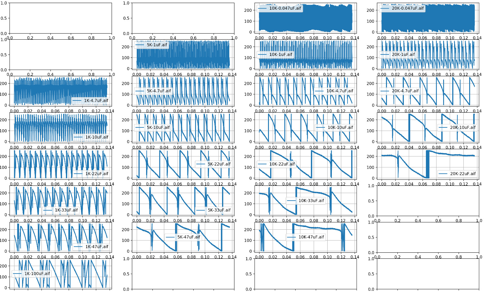
I worked through 22 different resistor / capacitor pairings so others don't have to brute-force it. Resistor values: 1KΩ, 5KΩ, 10KΩ, 20KΩ. Capacitors from 0.047µF to 47µF. Each pairing has a sound sample on the original post.
▸ Results
Final voicing: 2× (1KΩ + 22µF) and 2× (5KΩ + 10µF).